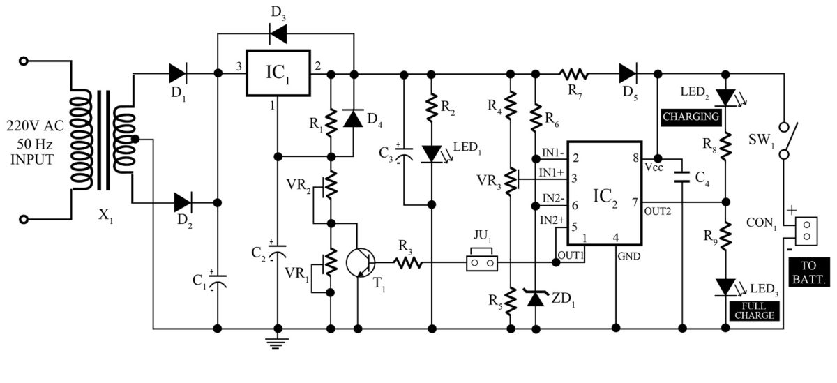
12v 7ah Battery Charger Circuit Diagram Pdf
- 12v 7ah Battery Charger Circuit Diagram Pdf File
- 12v Battery Charger Schematic
- Diy 12v Battery Charger Circuit
12v Battery Charger circuit with Overcharge Protection 12v Battery Charger circuit with Overcharge Protection This 12 battery charger circuit provides the Automatic cut off the facility when the battery gets fully charged. Before the use of this circuit, you need to adjust the Cut off voltage range for the auto cut. 12v battery charger with auto cut off circuit diagram. One 555 timer ic is used for detecting the voltage level and Relay is used to disconnect the AC input. 7808 voltage regulator is used for constant supply to the operation of the circuit to cut at a required fixed voltage.
Simple 12 volt battery charger circuit diagram designed by using few easily available components, and this circuit is suitable for different types of batteries needs 12 Volt. You can use this circuit to charge 12V SLA battery or 12V Gel cell battery and so on. This circuit is designed to provide charging current upto 3 amps and this circuit don’t have reverse polarity protection or over current protection so kindly test this circuit before stepping into battery charging.
Related Post– Lead Acid Battery Charger using LM317 3.Battery charger Using SCR. An automatic battery charger circuit using SCR is implemented in this project. It can be used to charge 12V batteries. Batteries with different potentials like 6V and 9V can also be charged by choosing appropriate components. The working of the circuit is as. Jun 20, 2020 Thank you for these interesting circuits, i am in the process of building 12v charger using IC L200but am finding it difficult to calculate Rx and Ry. This will be used to charge 12v 7.2 AH battery and some times two 12v 7.2 AH battery’s at the same time so will have to change Rx and Ry from time to time, an adjustable circuit would be great. Tag: 12v 7ah battery charger circuit diagram. Lead Acid Battery Charger Circuit. We know Lead Acid Battery is the most widely used rechargeable battery.
12v 7ah Battery Charger Circuit Diagram Pdf File
This Simple 12 volt Battery Charger Circuit Diagram gives you a outline design for the general battery charger and you can add additional features to this circuit like reverse polarity protection by placing a diode at the output. (Diode anode to output positive supply and diode cathode as output positive terminal) and over current protection setup using transistors. The following charger circuit just a Raw prototype to give 12 Volt output to battery.
Circuit Diagram
Components Required
- Step down transformer (0-14V AC / 3 Amps) – Choose depends on your requirements.
- Bridge Rectifier module BR1010
- Capacitors 0.01µF, 100µF/25V each one
- Resistor 1KΩ (Use 0.25W for normal LED)
- LED
Construction & Working

Use Required ampere Step down transformer for your target battery, here we have used 0-14V AC / 3 Amps Step down transformer and for AC to DC rectification we have used Bridge Rectifier module BR1010 which gives High efficient DC supply with high Current rating.
BR1010
This Bridge Rectifier module will have four terminals, two for AC supply input noted with sign wave and two terminals for DC output noted with positive and negative sign.
C1 and C2 capacitors are performing as filter in this circuit then LED indicates the presence of DC power supply at the output. Connect the target Battery at the output to get charged.
Simple 12 volt battery charger circuit diagram designed by using few easily available components, and this circuit is suitable for different types of batteries needs 12 Volt. You can use this circuit to charge 12V SLA battery or 12V Gel cell battery and so on. This circuit is designed to provide charging current upto 3 amps and this circuit don’t have reverse polarity protection or over current protection so kindly test this circuit before stepping into battery charging.
This Simple 12 volt Battery Charger Circuit Diagram gives you a outline design for the general battery charger and you can add additional features to this circuit like reverse polarity protection by placing a diode at the output. (Diode anode to output positive supply and diode cathode as output positive terminal) and over current protection setup using transistors. The following charger circuit just a Raw prototype to give 12 Volt output to battery.
Circuit Diagram
Components Required
- Step down transformer (0-14V AC / 3 Amps) – Choose depends on your requirements.
- Bridge Rectifier module BR1010
- Capacitors 0.01µF, 100µF/25V each one
- Resistor 1KΩ (Use 0.25W for normal LED)
- LED
Construction & Working
Use Required ampere Step down transformer for your target battery, here we have used 0-14V AC / 3 Amps Step down transformer and for AC to DC rectification we have used Bridge Rectifier module BR1010 which gives High efficient DC supply with high Current rating.
BR1010
This Bridge Rectifier module will have four terminals, two for AC supply input noted with sign wave and two terminals for DC output noted with positive and negative sign.
12v Battery Charger Schematic
C1 and C2 capacitors are performing as filter in this circuit then LED indicates the presence of DC power supply at the output. Connect the target Battery at the output to get charged.


